
For the FG40KK-1000G-90G-NG-S encoder, we offer a comprehensive custom-designed 1:1 replacement, created to assist users facing procurement obstacles or models that are no longer available on the market. Every critical detail—including mechanical sizing, shaft configuration, flange geometry, output format, and operating parameters—is replicated through a non-standard manufacturing process. This ensures that the replacement unit matches the original encoder perfectly, allowing it to be installed directly into existing systems without any changes to mounting brackets, wiring layouts, or control logic. The result is a smooth and reliable substitution that keeps industrial machinery running without interruption.
Our custom replacement solutions have gained strong traction globally, with orders coming from regions such as Southeast Asia, the Middle East, Russia, Indonesia, Ukraine, and South America. Clients value the operational stability of the customized encoders and the convenience of our streamlined 15-working-day production timeframe, which helps them avoid prolonged downtime and maintain continuity in demanding industrial environments. This international adoption highlights the dependability and practicality of our engineered replacement approach.
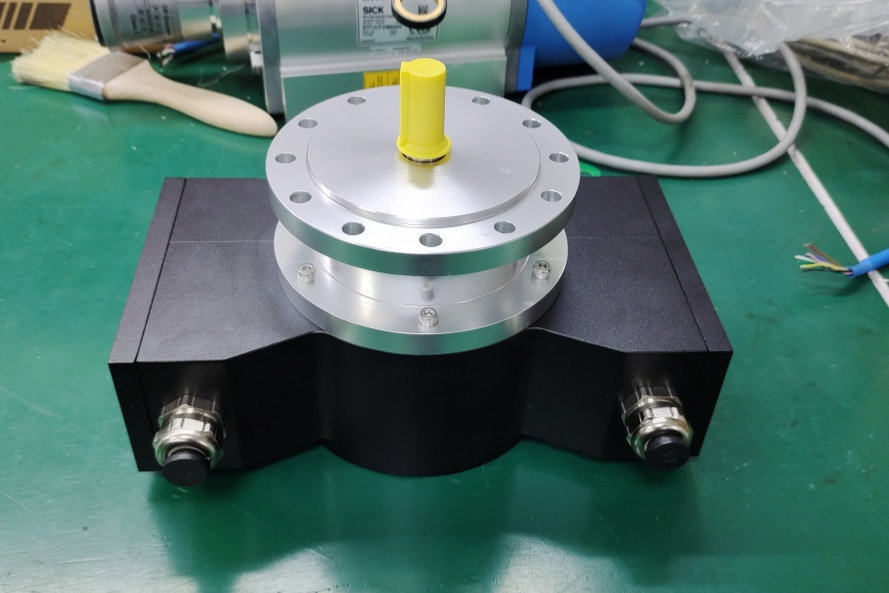
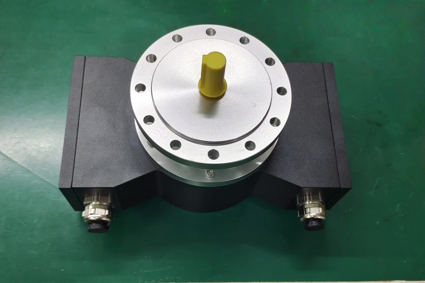
Replacement solution image
Technical data
| Parameter | Value |
|---|---|
| Pulse rates | |
| Standard pulse rates | 500, 600, 1000, 1024, 1200, 2000, 2048, 2400, 2500 |
| Special pulse rates | 4000, 4096, 4800, 5000, 8192, 10000, 12000, 16000, 16384, 20000, 25000, 40000, 50000 (further pulse rates according to customer specification) |
| Connection data | |
| Supply voltage | 12 V … 30 V DC (optional: 5 V DC) For UL and CSA Class 2 supplied |
| No load-current | approx. 50 mA at 24 V |
| Outputs | Current limited, short-circuit proof push-pull line driver with integrated impedance adaptation for 30 to 140 Ω lines |
| Pulse height (HTL) | approx. as supply voltage, output saturation voltage < 0.4 V at Iₗ 30 mA |
| Output current | max. 150 mA at 24 V (observe derating) |
| Internal resistance | 75 Ω bei 24 V |
| Slew rate | 200 V/μs with C_L 100 pF |
| Duty cycle | 1:1 ± 3 % for standard pulse rates 1:1 ± 5 % for special pulse rates up to 25000 pulses |
| Square wave displacement 0°, 90° | 90° ± 3 % for standard pulse rates 90° ± 5 % for special pulse rates up to 25000 pulses |
| Max. frequency | 200 kHz, Higher max. frequency on request |
| Special output voltage 5V (TTL) | |
| Pulse height | 5V, RS422-compatible (TIA/EIA-Standard) |
| Supply voltage | 12 … 30 V DC (optional: 5 V DC) For UL and CSA Class 2 supplied |
| Alternative Connection Data (from image(1)_1.png) | |
| Supply voltage | 5 V … 30 V DC For UL and CSA Class 2 supplied |
| No load-current | Approx. 120 mA at 5 V, approx. 50 mA at 24 V |
| Output signals | 2 sinusoidal signals A and B each with inverted signals Reference pulse with inverted signal Signal amplitude 1 V pp / R_L = 120 Ω Error signal and inverted signal Signal amplitude 5V |
| Resolution | 1024 signal periods |
| Duty cycle | 1 ± 0.1 |
| Phase shift A, B | 90° ± 1° |